

Introduction
In today’s energy-intensive industrial and commercial environments, inefficient power usage directly impacts operational costs. A low power factor—caused by inductive loads like motors, transformers, and lighting—results in wasted energy, increased system losses, and substantial utility penalties. The Automatic Power Factor Correction (APFC) Controller is the sophisticated control center designed to eliminate this inefficiency autonomously. By continuously analyzing the electrical network’s power factor and reactive power demand, this intelligent device automatically commands the switching of capacitor banks to inject precisely the required amount of reactive power. This process maintains an optimal, near-unity power factor, maximizing the usable capacity of your electrical infrastructure, reducing energy bills, and ensuring compliance with utility requirements—all without manual intervention.
Core Intelligence & Operational Excellence
1. Precision Measurement & Adaptive Control Logic
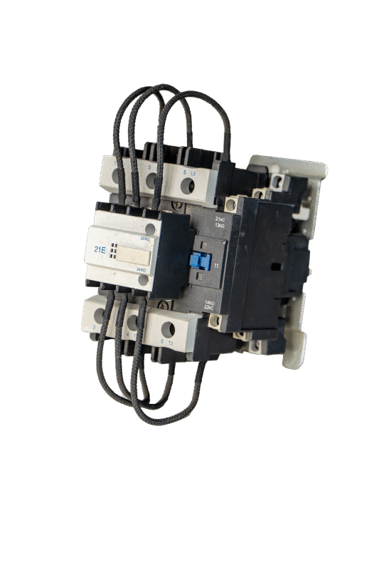
Feature: Equipped with high-accuracy Digital Signal Processors (DSP) for real-time measurement of voltage, current, active/reactive power, power factor, THD, and harmonics. Employs advanced control algorithms such as “FIFO” (First In, First Out), “LIFO” (Last In, First Out), or “Cyclical” switching to evenly distribute wear across all capacitor steps.
Benefit:** Ensures precise and dynamic compensation that reacts instantly to load changes. Intelligent switching logic extends the lifespan of contactors and capacitors by preventing repetitive switching of the same banks.
2. Comprehensive Protection & System Diagnostics
Feature: Built-in protective functions safeguard your capacitor investment: Overvoltage, Undervoltage, Overcurrent, Overtemperature (via PT100 input), Capacitor Bank Unbalance Detection, and Harmonic Distortion Limiting. Detailed event logging records all alarms, trips, and switching operations.
Benefit:** Prevents damage to costly capacitor banks and associated switching devices. Provides valuable diagnostic data for preventative maintenance, minimizing unplanned downtime and repair costs.
3. Versatile Configuration for Complex Systems
Feature: Supports configuration for systems with detuned (anti-harmonic) reactors (e.g., 7%, 14% impedance), allowing safe operation in networks with significant harmonic distortion. Can be set for “Reactive Power (kVar) Control” or “Power Factor (cos Φ) Control” modes.
Benefit:** Adapts to virtually any electrical environment, from simple commercial buildings to complex industrial plants with harmonic pollution. Offers flexibility to optimize control based on specific site requirements and utility tariff structures.
4. Advanced Human-Machine Interface (HMI) & Connectivity
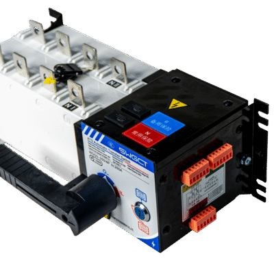
Feature: Features a large, backlit graphic LCD with multi-language support, providing clear display of all system parameters, status, and alarms. Standard RS485 communication port with Modbus RTU protocol enables seamless integration into Building Management Systems (BMS), Energy Management Systems (EMS), or SCADA.
Benefit:** Simplifies setup, monitoring, and data retrieval. Enables remote monitoring of energy savings performance, system health, and facilitates centralized control for multi-panel installations.
Technical Specifications (Representative)
| Parameter | Typical Specification |
|---|---|
| Supply Voltage | 110-240V AC/DC, 50/60Hz (Wide Range) |
| Measurement Voltage | 110V / 220V / 380V / 400V (PT or Direct) |
| Measurement Current | 0-5A AC (via CTs) |
| Control Outputs | 6, 8, 10, 12, 14, 16, 18, 20 Channels (Transistor or Relay) |
| Target Power Factor | Adjustable, typically 0.90 to 1.00 (Inductive/Capacitive) |
| Control Modes | PF (cos Φ) Control, kVar Control, Current Control |
| Switching Logic | FIFO, LIFO, Cyclic, Automatic Strategy Selection |
| Harmonics Analysis | Displays up to the 31st harmonic (Voltage & Current THD%) |
| Display | Graphic LCD with LED Indicators |
| Communication | RS485 (Modbus RTU), Optional: Ethernet (Modbus TCP, Profinet) |
| Enclosure Rating | IP40 (Panel Mounted) |
| Standards | IEC 61921, GB/T 22582, CE, RoHS |
Primary Applications
-
Industrial Manufacturing Plants: Compensating for large induction motors, welding machines, and inductive furnaces.
-
Commercial Buildings & Shopping Malls: Correcting low PF caused by HVAC systems, lighting ballasts, and escalators.
-
Water & Wastewater Treatment Facilities: Managing reactive power demand from large pump and blower motors.
-
Data Centers: Optimizing power quality and efficiency for UPS systems and cooling infrastructure.
-
Renewable Energy Stations (Solar/Wind): Providing grid-side reactive power support to meet utility interconnection requirements.
Value Proposition
-
Significant Cost Savings: Reduces or eliminates utility power factor penalties and decreases I²R losses in cables and transformers, leading to direct bottom-line savings.
-
Enhanced System Capacity: By reducing reactive current, it effectively frees up capacity in existing transformers, cables, and switchgear, potentially deferring costly upgrades.
-
Improved Voltage Stability & Power Quality: Compensation helps stabilize bus voltage, improving the performance and longevity of connected equipment.
-
Sustainable Operation: Lowers the carbon footprint of your facility by reducing overall system current and associated distribution losses.
System Design & Commissioning
-
Professional Sizing Required: Proper selection of CT ratio, capacitor step size (kVar), and controller configuration is essential for optimal performance. Our engineering team can provide support.
-
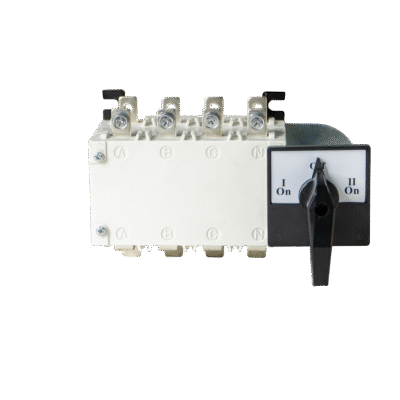
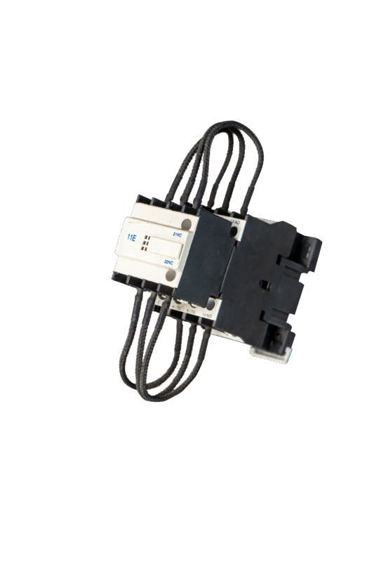
Easy Integration: DIN-rail mounting design and pre-configured wiring terminals simplify installation within APFC panels.
-
Ongoing Support: Comprehensive user manuals, configuration software, and technical support ensure smooth commissioning and long-term operation.


Valoraciones
No hay valoraciones aún.